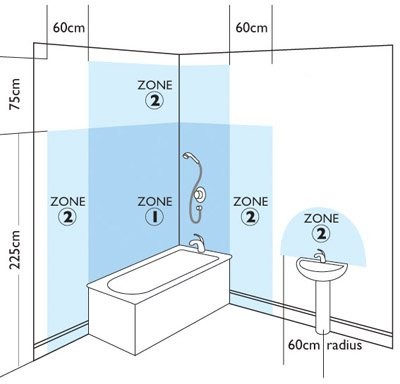
Iee Wiring Regulations.
Iee Wiring Regulation.
Of Iee Wiring Regulations Part P Building Regulations 17th Edition.
An Amendment To Bs 7671 2001 The Iee Wiring Regulations States That.
Iee Wiring Regulations Inspection Testing And Certification Iee.
17th Edition Iee Wiring Regulations Inspection Testing And.
Iee Wiring Regulations 16th Edition Or Contact A Qualified Electrician.
Iet Wiring Regulations 17th Edition Bs7671 2008 2011.
Electrician S Guide To The 17th Edition Of The Iee Wiring Regulations.
Guidance Note 3 To Iee Wiring Regulations Bs7671 Inspection And.
Home » Archives for May 2013
Friday, May 31, 2013
Wiring Regulationsinspectiontesting Certification
Friday, May 17, 2013
9V Portable Headphone Amplifier

After several requests of the correspondents, the decision to design a headphone amplifier 9V power was finally taken. The main requirement was to feed the circuit by a common, PP3 (transistor radio) alkaline batteries. Therefore, the circuit implementation of a low current draw was absolutely necessary, while retaining high quality.
The emergence of low-noise 5534 operational amplifier at a reasonable price was much appreciated by audio designers. Now it is difficult or impossible to design a specific phase that has the performance of 5534, without the complexity unacceptable. 5534 operational amplifiers are available from various sources, in a conventional 8-pin dil format. This version is internally compensated for gains of three or more, but requires a small external capacitor (5-15pF) for unity gain stability. The 5532 is a convenient pack of two 5534s in an 8-pin device with internal unity gain compensation, since there are no spare pins.
The 5534 / 2 is a low distortion and low noise device also has the ability of low-impedance load to full voltage swing, while maintaining low distortion. It is fully output short-circuit. Therefore, this circuit is carried out with a single 5532 chip forming a pair of stereo amplifiers, invest, have a current gain of about 3.5 alternating and capable of delivering up to 3.6 V peak to peak 32 Ohm load (corresponding to 50mW RMS) less than 0.025% total harmonic distortion (1 kHz and 10 kHz).
Considering that the average current drawing a power of 15 mW per channel is about 12-13mA (both channels driven), this headphone amplifier will become a "must" for many DIY enthusiasts who need a device High quality, high performance laptop.
Monday, May 13, 2013
Sequential Turn Lights Driver
This device was designed on request and allows sequential operation of four Leds either to left or right direction, obtained by means of a 7555 CMos timer IC (IC1) wired as an astable multivibrator driving a Decade counter (IC2). This IC is set to count a sequence of four by connection of pin #10 to pin #15, but any sequence count in the 2-10 range can be set by choosing the appropriate pin connection. Obviously, LEDs, Transistors and their respective Base-limiting resistors must also be added or omitted accordingly.R1 is a variable resistor (Trimmer), used to set the desired speed of the LEDs. SW1 is a change-over switch that should already exist in your motorcycle, having a center-off position and Turn-left and Turn-right positions.D1, D3, D5 and D7 are the Turn-left LEDs; D2, D4, D6 and D8 are the Turn-right LEDs.
Parts:
R1_____________500K 1/2W Trimmer Cermet or Carbon R2______________47K 1/4W Resistor
R3,R4____________1K 1/4W Resistors
R5,R6,R7,R8_____10K 1/4W Resistors
C1_______________1µF 63V Polyester or electrolytic capacitor C2_____________220µF 25V Electrolytic capacitor
D1-D8__________LEDs Yellow ultra-bright types
Q1,Q2,Q3,Q4___BC337 45V 800mA NPN Transistors
IC1____________7555 or TS555CN or TLC555CP CMos Timer IC IC2____________4017 Decade counter with 10 decoded outputs IC SW1____________Vehicle Turn Lights switch (See Comments) Battery_________12V Vehicle battery
Sunday, May 5, 2013
5 8 Watt Audio Power Amplifier

Fig 1. TA7222AP pin out
| Pin | Name | Description |
|---|---|---|
| 1 | Vcc | Supply Voltage |
| 2 | RR | Ripple Reject |
| 3 | MC | Muting control |
| 4 | OP | AF Signal Input |
| 5 | FB | FB Filter |
| 6 | GA | Gain adjust |
| 7 | GND | Ground |
| 8 | GND | Ground |
| 9 | OP | AF Output |
| 10 | BS | BootStrap |

Fig 2. schematic for 5.8 watt audio power amplifier


