Showing posts with label electronic. Show all posts

Tuesday, December 17, 2013

Electronic Security System

This reliable and easy-to-operate electronic security system can be used in banks, factories, commercial establishments, houses, etc. The system comprises a monitoring system and several sensing zones. Each sensing zone is provided with a closed-loop switch known as sense switch. Sense switches are fixed onthedoors of premises under security and connected to the monitoring system. As long as the doors are closed, sense switches are also closed. The monitoring system can be installed at a convenient central place for easy operation.

Fig. 1 shows the monitoring circuit only for zone 1 along with the common alarm circuit. For other zones, the monitoring circuit is identical, with only the prefixes of components changing as per zone number. Encircled points A, B, and C of each zone monitoring circuit need to be joined to the corresponding points of the alarm circuit (upper half of Fig. 1).

Fig. 1: Monitoring Circuit Along with the Alarm Circuit diagram

Monitoring circuit along with the alarm circuit

When zone 1 sensing switch S11, zone switch S1 are all on, pnp transistor T12 reverse biases to go in cut-off condition, with its collector at around 0 volt. When the door fitted with sensor switch S11 is opened, transistor T12 gets forward biased and it conducts. Its collector voltage goes high, which forward biases transistor T10 via resistor R10 to turn it on. (Capacitor C10 serves as a filter capacitor.) As a result, the collector voltage of transistor T10 falls to forward bias transistor T11, which conducts and its collector voltage is sustained at a high level. Under this latched condition, sensor switch S11 and the state of transistor T12 have no effect. In this state, red LED11 of the zone remains lit.

Simultaneously, the high-level voltage from the collector of transistor T11 via diode D10 is applied to VDD pin 5 of siren sound generator IC1 (UM3561) whose pin 2 is grounded. Resistor R3 connected across pins 7 and 8 of IC1 determines the frequency of the in-built oscillator. As a result, IC1 starts generating the audio signal output at pin 3. The output voltage from IC1 is further amplified by Darlington pair of transistors T1 and T2. The amplified output of the Darlington pair drives the loudspeaker whose output volume can be controlled by potentiometer VR1. Capacitor C1 serves as a filter capacitor.

Fig. 2: Physical Layout of Sensors and Monitoring Alarm System:

Physical layout of sensors and monitoring alarm system

You can alter the alarm sound as desired by changing the connections of IC1 as shown in the table.

F99_table

The circuit continues to sound the alarm until zone door is closed (to close switch S11) and the reset switch is pressed momentarily (which causes transistor T10 to cut off, returning the circuit to its initial state). The system operates off a 3V DC battery or recharging battery with charging circuit or battery eliminator. If desired, more operating zones can be added. Initially keep the monitoring system switch S1 off. Keep all the zone doors fixed with sensing switches S11, S21, S31, S41, etc closed. This keeps the sensing switches for respective zones in closed position. Also keep zone slide switches S12, S22, S32, S42, etc in ‘on’ position.

This puts the system in operation, guarding all the zone doors.Now, if the door of a particular zone is opened, the monitoring system sounds an audible alarm and the LED corresponding to the zone glows to indicate that the door of the zone is open. The alarm and the LED indication will continue even after that particular door with the sensing switch is immediately closed, or even if that switch is removed/damaged or connecting wire is cut open. Any particular zone in the monitoring system can be put to operation or out of operation by switching on or switching off the corresponding slide switch in the monitoring system.

Source : http://www.ecircuitslab.com/2012/05/electronic-security-system.html
Friday, October 4, 2013

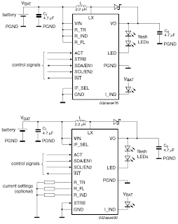
SSL3250A PHOTO FLASH LED DRIVER ELECTRONIC DIAGRAM

SSL3250A PHOTO FLASH LED DRIVER ELECTRONIC DIAGRAM

These properties caused this device has long battery life and low power strain. Another features that this device has are protecting the battery and LED from overloading, trouble free operation such as overtemperature, over voltage, time-out function, undervoltage lockout, and feedback shorted protection.

Tuesday, September 24, 2013

AUTOMATIC AIRFLOW DETECTOR ELECTRONIC DIAGRAM


AUTOMATIC AIRFLOW DETECTOR ELECTRONIC DIAGRAM

Sensor used in this circuit is a bulb filament. If there is no airflow, the filament resistance would give low value. On the other hand, if there is airflow, the filament resistance would varies. The variation of the resistance is caused by the heat difference between filament. It also effects to the voltage variation passing through that filament. That voltage difference will be processed by LM339 op-amp and displayed by the LED.

Parts list :


  •     LED1 : LED 5mm
  •     IC1 volt regulator : LM7805
  •     Polar Capacitor C1 : 47 uF/15V
  •     Resistor R1 : 100 ohm
  •     Resistor R2 : 470 ohm
  •     Resistor R3 : 10k ohm
  •     Potensiometer R4 : 100k ohm
  •     Resistor R5 : 1k ohm
  •     IC2 op-amp : LM339
  •     Bulb filament
  •     Power supply/battery 12V


Tuesday, September 10, 2013

Digital Electronic Lock Circuit Diagram

This Digital Electronic Lock Circuit Diagram shown below uses 4 common logic ICs to allow controlling a relay by entering a 4 digit number on a keypad. The first 4 outputs from the CD4017 decade counter (pins 3,2,4,7) are gated together with 4 digits from a keypad so that as the keys are depressed in the correct order, the counter will advance. As each correct key is pressed, a low level appears at the output of the dual NAND gate producing a high level at the output of the 8 input NAND at pin 13.

Read : Cheap Bicycle Alarm Schematics Circuit

Digital Electronic Lock Circuit Diagram

Digital Electronic Lock Circuit Diagram

The momentary high level from pin 13 activates a one shot circuit which applies an approximate 80 millisecond positive going pulse to the clock line (pin 14) of the decade counter which advances it one count on the rising edge.

Read : Emergency Light and Alarm Circuit Diagram

A second monostable, one shot circuit is used to generate an approximate 40 millisecond positive going pulse which is applied to the common point of the keypad so that the appropriate NAND gate will see two logic high levels when the correct key is pressed (one from the counter and the other from the key). The inverted clock pulse (negative going) at pin 12 of the 74C14 and the positive going keypad pulse at pin 6 are gated together using two diodes as an AND gate (shown in lower right corner).

Read : Burglar Alarm With Timed Shutoff Circuit Diagram

The output at the junction of the diodes will be positive in the event a wrong key is pressed and will reset the counter. When a correct key is pressed, outputs will be present from both monostable circuits (clock and keypad) causing the reset line to remain low and allowing the counter to advance. However, since the keypad pulse begins slightly before the clock, a 0.1uF capacitor is connected to the reset line to delay the reset until the inverted clock arrives.

Read : 5 Zone alarm Circuit Diagram

The values are not critical and various other timing schemes could be used but the clock signal should be slightly longer than the keypad pulse so that the clock signal can mask out the keypad and avoid resetting the counter in the event the clock pulse ends before the keypad pulse. The fifth output of the counter is on pin 10, so that after four correct key entries have been made, pin 10 will move to a high level and can be used to activate a relay, illuminate an LED, ect. At this point, the lock can be reset simply by pressing any key. The circuit can be extended with additional gates (one more CD4011) to accept up to a 8 digit code.

Read :  Alarm Control Keypad Circuit Diagram

The 4017 counting order is 3 2 4 7 10 1 5 6 9 11 so that the first 8 outputs are connected to the NAND gates and pin 9 would be used to drive the relay or light. The 4 additional NAND gate outputs would connect to the 4 remaining inputs of the CD4068 (pins 9,10,11,12). The circuit will operate from 3 to 12 volts on 4000 series CMOS but only 6 volts or less if 74HC parts are used. The circuit draws very little current (about 165 microamps) so it could be powered for several months on 4 AA batteries assuming only intermittent use of the relay.