This converter may help if just the serial port on a personal computer is free, whereas the printer needs a parallel (Centronics) port. It converts a serial 2400 baud signal into a parallel signal. The TxD line, pin 3, CTS line, pin 8 and the DSR line, pin 6, of the serial port are used - see diagram. The CTS and DSR signals enable handshaking to be implemented. Since the computer needs real RS232 levels, an adaptation from TTL to RS232 is provided in the converter by a MAX232. This is an integrated level converter that transforms the single +5V supply into a symmetrical ±12V one. The serial-to-parallel conversion is effected by IC1. This is essentially a programmed PIC controller that produces a Centronics compatible signal from a 2400 baud serial signal (eight data bits, no parity, one stop bit). The IC also generates the requisite control signals. If there is a delay on the Centronics port, the RS232 bitstream from the computer may be stopped via the Flow signal (pin 17). This ensures that no data is lost. The controller needs a 4 MHz ceramic resonator, X1.
Home » Archives for September 2013
Monday, September 30, 2013
Serial To Parallel Converter
Thursday, September 26, 2013
Simple Battery Isolator
This circuit is even simpler and employs a 6V feed from one of the stator connections on the vehicle’s alternator. This is connected to a 6V automotive relay (RLY1) which controls a Continuous Duty Solenoid (RLY2). This solenoid electrically connects or isolates the batteries. When the engine is started and the alternator stator voltage rises, the 6V relay turns on. This turns on the Continuous Duty Solenoid to connect the two batteries in parallel. As long as the engine is running, the vehicle’s alternator will maintain charge in both batteries. When the engine is shut down, the alternator stator voltage drops and the Continuous Duty Solenoid switches off, thus isolating the second battery from the vehicle’s electrical system. Provided that camping accessories are only connected to the second battery, the main battery should never discharge. Because the concept is entirely dependent upon the alternator’s stator output voltage, you cannot forget to turn the system on or off as it happens automatically.
Tuesday, September 24, 2013
AUTOMATIC AIRFLOW DETECTOR ELECTRONIC DIAGRAM
Sensor used in this circuit is a bulb filament. If there is no airflow, the filament resistance would give low value. On the other hand, if there is airflow, the filament resistance would varies. The variation of the resistance is caused by the heat difference between filament. It also effects to the voltage variation passing through that filament. That voltage difference will be processed by LM339 op-amp and displayed by the LED.
Parts list :
- LED1 : LED 5mm
- IC1 volt regulator : LM7805
- Polar Capacitor C1 : 47 uF/15V
- Resistor R1 : 100 ohm
- Resistor R2 : 470 ohm
- Resistor R3 : 10k ohm
- Potensiometer R4 : 100k ohm
- Resistor R5 : 1k ohm
- IC2 op-amp : LM339
- Bulb filament
- Power supply/battery 12V
Sunday, September 22, 2013
Loudspeaker Protector Monitors Current
This circuit uses a 0.1O 1W resistor connected in series with the output of a power amplifier. When the amplifier is delivering 100W into an 8O load, the resistor will be dissipating 1.25W. The resulting temperature rise is sensed by a thermistor which is thermally bonded to the resistor. The thermistor is connected in series with a resistor string which is monitored by the non-inverting (+) inputs of four comparators in an LM339 quad comparator. All of the comparator inverting inputs are connected to an adjustable threshold voltage provided by trimpot VR1. As the thermistor heats up, its resistance increases, raising the voltage along the resistor ladder.
When the voltage on the non-inverting input of each comparator exceeds the voltage at its inverting input, the output switches high and illuminates the relevant LED. NOR gate latches are connected to the outputs of the third and fourth comparators. When the third comparator switches high, the first latch is set, turning on Q1 and relay 1. This switches in an attenuation network (resistors RA & RB) to reduce the power level. However, if the power level is still excessive, comparator 4 will switch, setting its latch and turning on Q2 and relay 2.
This disconnects the loudspeaker load. The thermistor then needs to cool down before normal operation will be restored. The values of R1-R4 depend on the thermistor used. For example, if a thermistor with a resistance of 1.5kO at 25°C is used, then R1 could be around 1.5kO and R2, R3 and R4 would each be 100O (depending the temperature coefficient of the thermistor). The setup procedure involves connecting a sinewave oscillator to the input of the power amplifier and using a dummy load for the output. Set the power level desired and adjust trimpot VR1 to light LED1. Then increase the power to check that the other LEDs light at satisfactory levels.
Friday, September 20, 2013
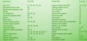
Fuse Box BMW 328i Central 1999 Diagram
Fuse Box BMW 328i Central 1999 Diagram - Here are new post for Fuse Box BMW 328i Central 1999 Diagram.
Fuse Box BMW 328i Central 1999 Diagram
Fuse Panel Layout Diagram Parts: ABS system, adjustment driver seat, adjusment passenger seat, air bag, air conditioner, blower, brake light, central locking system, cigar lighter, electric fan, electric seat heating, engine control, folding outside mirror, fog light, garage door opener, heated outside mirror, heated rear window, heated spray nozzle, horn, immobilizer, instrument cluster.
Thursday, September 12, 2013
Kawasaki KLR 250 Carb Cleaning Information
 If you were to browse any KLR250 related forum the most common ailment youd hear owners complain about is some type of starting or running problem, usually carburetor related. These problems arent biased to just the KLR, any carbureted bike can experience them. Theyre usually due to dirt in the fuel clogging a jet, or varish gumming everything up. The only solution is to remove the carb from the bike and give it a thorough cleaning and inspection. Thats what this article is meant to do, show you the basics of the KLR250 carburetor and give a quick run through on how to clean it.We wont get into how a carb works, but if youre interested in learning more check out The Care and Feeding of the Keihn Carb.
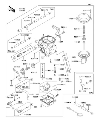 The KLR 250 comes with a Keihn CVK34 carburetor. Dont let the parts diagram to the left fool you, CVK34 is a very simple design. To clean the carb youll need to remove it from the bike. Probably one of the more painful processes whenever you have to work on your bikes carb is trying to get it out of the bike. At the very least itll require removing the side plastics, seat, and fuel tank, though we have found that unbolting the exhaust muffler and the top bolts of the subframe (the part the seat bolts to) make things easier by allowing you to pivot the entire subframe backwards giving better access to the carb. Once youve gotten to the carb follow these steps to disconnect and remove it.
Removal:
1. Turn off the fuel petcock on the fuel tank
2. Place a container under the fuel drain hose. That is the hose which leads from the fuel drain screw to just in front of the rear wheel.
3. Open drain screw, located on the bottom right side of the carb (on the float bowl) and allow all of the fuel to drain from the carb.
4. Remove the fuel line from the left side of the carb (black rubber line from the fuel tank)
5. Remove the throttle cables, one screw holds the bracket in place.
6. Carefully unscrew the plastic choke cable nut from the left side of the carburetor. This is where the choke cable screws into the carb. The plastic nut is very fragile so be careful!
7. Loosen the clamp on the front side of the carb holding it to the engine.
8. Remove the rear carb to airbox tube
OK now you should have the carb out of the bike and holding it in your hands. Next step is tearing it down while being very careful not to lose or damage anything in the process.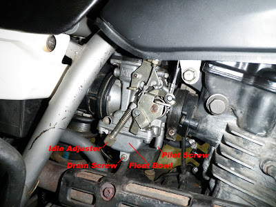 Teardown:
1. Remove the four screws on the plastic piece on the top of the carb. Underneath there should be a diaphragm, spring, slide, needle and white piece of plastic. Make a mental note of the order of those parts (slide, needle, white plastic piece, spring) and remove them. Be careful not to tear the rubber diaphragm.
2. Remove the float bowl. That is the metal bowl on the bottom of the carb, held in place with four screws. Be careful when removing it as the float and needle valve can fall out. Make a note of the position of the float and needle and remove them.
3. Next step is to unscrew the main and pilot jets from the carb body. (see diagram above for their location)
Pilot Screw Info:
The KLRs carb has a pilot mixture screw which controls the amount of fuel that enters the engine while at idle. However to stop owners from fiddling with it Kawasaki covered the screw with a small tin cap. The only way to get to this screw is to carefully drill a small hole in the tin cap and then pry it off with a small screw driver. The utmost care must be taken so you dont screw all of the way through to the pilot screw itself. Once the screw is accessible then you can remove it. There should be an o-ring, washer, and spring on the end of it, note their order and set them to the side.
Cleaning:
Thats about all you need to disassemble. Wasnt that hard was it? Now its time to clean everything. Just about everyone has their own way of doing this but what we suggest is buying a few bottles of carb cleaner (the kind you pour in your cars fuel tank) and a couple cans of spray type carb cleaner that have the small plastic tubes on them. Fill a small container with the carb cleaner (bottle type) and soak all of the metal parts in it, including the carburetor body. Note: Do not use either carb cleaner on any plastic or rubber parts, itll eat them. What youre trying to accomplish is the removal of all varnish from inside the carb body, and jets. After theyve soaked for a couple of hours its time to spray out all of the small passages in the carb body, and the tiny holes in jets with the spray type carb cleaner and then follow it up with a blast of compressed air. Youre trying to make sure there is nothing clogging up those small holes, you leave one grain of sand behind and youll be doing this again so be diligent! By this point you should have a sparkling clean carburetor, all that is left to do is reassemble everything.
Reassembly:
There isnt much to say here, just reassemble everything in the reverse order you took it apart. When the time comes to re-install the pilot screw make sure the o-ring, washer, and spring are in place and screw it in all of the way and back out two full turns. (further adjustment may be needed but this is a good starting point) When you re-install the slide components be careful not to pinch or tear the rubber diaphragm. Float Adjustment:
While you have the carb apart and cleaned this is the perfect time to check the float height adjustment. Simply install the float and needle valve onto the carb body and hold it as shown in the diagram to the left. You want the needle to be lying on its seat but not pushed down. To check for proper adjustment measure from the float bowl mating surface, and the top of the float. (4) The adjustment should be 17mm. If you find its not 17mm then you correct it by ever so slightly bending the float bowl tang with a pair of needle nose pliers. (see arrow in this picture) Small adjustment result in big changes in the float height, so go easy. Once youve got it to 17mm youre all set.
Thats it! Now re-install the carb back in the bike and youre good to go!
Image Sources: Gadjetjq.com - KLR650.net - Kawasaki.com
Note: The top image is of a CVK40. While it is a different carburetor than the CVK34 in the KLR 250 their layouts are almost identical.
Tuesday, September 10, 2013
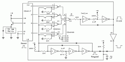
Digital Electronic Lock Circuit Diagram
Read : Cheap Bicycle Alarm Schematics Circuit
Digital Electronic Lock Circuit Diagram
Read : Emergency Light and Alarm Circuit Diagram
Read : Burglar Alarm With Timed Shutoff Circuit Diagram
Read : 5 Zone alarm Circuit Diagram
Read : Alarm Control Keypad Circuit Diagram
Wednesday, September 4, 2013
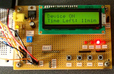
00 To 99 Minute Timer Using PIC16F628A Microcontroller
As I mentioned earlier, the microcontroller used in this project is PIC16F628A running at 4.0 MHz clock using an external crystal. An HD44780 based 16×2 character LCD is the main display unit of the project where you can watch and set the timer duration using tact switch inputs. There are three tact switches connected to RB0 (Start/Stop), RB1 (Unit), and RB2 (Ten) pins. You can select the timer interval from 0-99 min using Unit and Ten minute switches. The Start/Stop switch is for toggling the timer ON and OFF. When the timer gets ON, a logic high signal appears on the RA3 pin, which can be used to switch on a Relay. The circuit diagram of this project is described below.
When the desired time is set, press the Start/Stop switch to turn ON the timer. The RA3 pin goes high (LED glows) and the count down begins. When the timer is ON, the remaining time is also shown on the LCD screen. When the time elapsed, the timer stops and the LED turns OFF. You can interrupt and stop the timer at anytime by pressing the Start/Stop switch once more. The firmware for PIC is developed using mikroC Pro for PIC compiler. The use of Timers are avoided for simplicity. The time delays are created using the Delay_ms() function of mikroC, which seems to give reasonably accurate timing delays.
Download Mikroc Source Code And HEX File
Monday, September 2, 2013
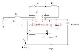
Metal Detector Schematic Using CS209A
Metal Detector Schematic Circuit Diagram
FOr this electronic project youll need the following electronic parts: R1=220ohms, R2,R5=10k,R3=1k ,C1,C3=2.2nF; C2=10uF. Entire circuit can be powered from a 9 volts battery.


