Showing posts with label diagram. Show all posts

Friday, January 10, 2014

12V Latch Circuit Diagram

This circuit controls a solenoid by the operation of a single push-button switch. The circuit will supply loads of over 1 A and can be operated up to a maximum speed of once every 0.6 second. When power is first applied to the circuit, the solenoid will always start in its off position. Other features of the circuit are its automatic turn-off, if the load is shorted, and its virtually zero-power consumption when off.

12V Latch Circuit Diagram

12V Latch Circuit Diagram

Friday, October 4, 2013

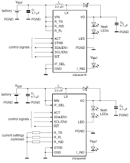
SSL3250A PHOTO FLASH LED DRIVER ELECTRONIC DIAGRAM

SSL3250A PHOTO FLASH LED DRIVER ELECTRONIC DIAGRAM

These properties caused this device has long battery life and low power strain. Another features that this device has are protecting the battery and LED from overloading, trouble free operation such as overtemperature, over voltage, time-out function, undervoltage lockout, and feedback shorted protection.

Tuesday, September 24, 2013

AUTOMATIC AIRFLOW DETECTOR ELECTRONIC DIAGRAM


AUTOMATIC AIRFLOW DETECTOR ELECTRONIC DIAGRAM

Sensor used in this circuit is a bulb filament. If there is no airflow, the filament resistance would give low value. On the other hand, if there is airflow, the filament resistance would varies. The variation of the resistance is caused by the heat difference between filament. It also effects to the voltage variation passing through that filament. That voltage difference will be processed by LM339 op-amp and displayed by the LED.

Parts list :


  •     LED1 : LED 5mm
  •     IC1 volt regulator : LM7805
  •     Polar Capacitor C1 : 47 uF/15V
  •     Resistor R1 : 100 ohm
  •     Resistor R2 : 470 ohm
  •     Resistor R3 : 10k ohm
  •     Potensiometer R4 : 100k ohm
  •     Resistor R5 : 1k ohm
  •     IC2 op-amp : LM339
  •     Bulb filament
  •     Power supply/battery 12V


Friday, September 20, 2013

Fuse Box BMW 328i Central 1999 Diagram

Fuse Box BMW 328i Central 1999 Diagram - Here are new post for Fuse Box BMW 328i Central 1999 Diagram.

Fuse Box BMW 328i Central 1999 Diagram


Fuse Box BMW 328i Central 1999 Diagram

Fuse Panel Layout Diagram Parts: ABS system, adjustment driver seat, adjusment passenger seat, air bag, air conditioner, blower, brake light, central locking system, cigar lighter, electric fan, electric seat heating, engine control, folding outside mirror, fog light, garage door opener, heated outside mirror, heated rear window, heated spray nozzle, horn, immobilizer, instrument cluster.

Tuesday, September 10, 2013

Digital Electronic Lock Circuit Diagram

This Digital Electronic Lock Circuit Diagram shown below uses 4 common logic ICs to allow controlling a relay by entering a 4 digit number on a keypad. The first 4 outputs from the CD4017 decade counter (pins 3,2,4,7) are gated together with 4 digits from a keypad so that as the keys are depressed in the correct order, the counter will advance. As each correct key is pressed, a low level appears at the output of the dual NAND gate producing a high level at the output of the 8 input NAND at pin 13.

Read : Cheap Bicycle Alarm Schematics Circuit

Digital Electronic Lock Circuit Diagram

Digital Electronic Lock Circuit Diagram

The momentary high level from pin 13 activates a one shot circuit which applies an approximate 80 millisecond positive going pulse to the clock line (pin 14) of the decade counter which advances it one count on the rising edge.

Read : Emergency Light and Alarm Circuit Diagram

A second monostable, one shot circuit is used to generate an approximate 40 millisecond positive going pulse which is applied to the common point of the keypad so that the appropriate NAND gate will see two logic high levels when the correct key is pressed (one from the counter and the other from the key). The inverted clock pulse (negative going) at pin 12 of the 74C14 and the positive going keypad pulse at pin 6 are gated together using two diodes as an AND gate (shown in lower right corner).

Read : Burglar Alarm With Timed Shutoff Circuit Diagram

The output at the junction of the diodes will be positive in the event a wrong key is pressed and will reset the counter. When a correct key is pressed, outputs will be present from both monostable circuits (clock and keypad) causing the reset line to remain low and allowing the counter to advance. However, since the keypad pulse begins slightly before the clock, a 0.1uF capacitor is connected to the reset line to delay the reset until the inverted clock arrives.

Read : 5 Zone alarm Circuit Diagram

The values are not critical and various other timing schemes could be used but the clock signal should be slightly longer than the keypad pulse so that the clock signal can mask out the keypad and avoid resetting the counter in the event the clock pulse ends before the keypad pulse. The fifth output of the counter is on pin 10, so that after four correct key entries have been made, pin 10 will move to a high level and can be used to activate a relay, illuminate an LED, ect. At this point, the lock can be reset simply by pressing any key. The circuit can be extended with additional gates (one more CD4011) to accept up to a 8 digit code.

Read :  Alarm Control Keypad Circuit Diagram

The 4017 counting order is 3 2 4 7 10 1 5 6 9 11 so that the first 8 outputs are connected to the NAND gates and pin 9 would be used to drive the relay or light. The 4 additional NAND gate outputs would connect to the 4 remaining inputs of the CD4068 (pins 9,10,11,12). The circuit will operate from 3 to 12 volts on 4000 series CMOS but only 6 volts or less if 74HC parts are used. The circuit draws very little current (about 165 microamps) so it could be powered for several months on 4 AA batteries assuming only intermittent use of the relay.

Tuesday, August 13, 2013

Simple 500W Audio Power Amplifier Circuit Diagram with Transistor

We take transistor MJL2194 and MJL2193 for drive output signal.so the amp has a capacity for enormous instantaneous current ability.

 Simple 500W Audio Power Amplifier Circuit Diagram with Transistor

I think, it is useful for you to apply the circuit with your sound devices.

Circuit Functional
I use the -85 volt when the output current is supplied to the drive 350 to 340 very hot. Increase the output current, but it was too cold. The output to heat up faster than a normal open it. Sounds obvious, but sound quality is quite good.

I recomment it by turning out for the evening. If the drive is mounted on the metal part out.

I think simple. View full above, the observation that R 30 ohm then the voltage across the 0.86 V show that the new through its 29 mA if you add a file to / – 85 V, and suppose that the voltage across the component body. It was the same in both the R 30 ohm to get a very light 5 0.86 = 5.86 V and the current I will be 5.86/30 = 0.195 A = 195 mA, and the specification of mje340. mje350 get Ic (max) = 500 mA, so it is natural for it to heat up. Actually, it is not necessary to adhere to sync tr output should be interested in the following two tr power drive is better. For VR should be R300 .

Thursday, August 1, 2013

1997 Audi A4 Air Conditioning System Circuit and Schematic Diagram on 1997 Audi A4


The following wiring diagram / scematic shows 1997 Audi A4 air conditioning system Circuit and Schematic Diagram which consists of A/C control head, footwell/defroster, flap motor and sensor, temperature regulator, motronic engine control module, interior temperature fan and sensor, digital outside air temperature/ transmission range selector lever display, sunlight photo sensor, A/C compressor speed sensor, outside temperature sensor, fresh air intake duct, fuse panel and instrument cluster, A/C compressor clutch relay, central flap motor and sensor, back pressure motor and sensor, center outlet temperature sensor, fresh air blower, coolant fan control thermal switch, coolant fan, and coolant fan control relay. 


For detailed information about 1997 Audi A4 Air Conditioning System Circuit and Schematic Diagram here (diagram 1 and diagram 2, source: autolib.diakom.ru)