Electronics textbooks will tell you that a non-inverting opamp normally cannot be regulated down to 0 dB gain. If zero output is needed then it is usual to employ an inverting amplifier and a buffer amp in front of it, the buffer acting as an impedance step-up device. The circuit shown here is a trick to make a non-inverting amplifier go down all the way to zero output. The secret is a linear-law stereo potentiometer connected such that when the spindle is turned clockwise the resistance in P1a increases (gain goes up), while the wiper of P1b moves towards the opamp output (more signal). When the wiper is turned anti-clockwise, the resistance of P1a drops, lowering the gain, while P1b also supplies a smaller signal to the load. In this way, the output signal can be made to go down to zero.
Home » Archives for October 2013
Tuesday, October 8, 2013
Zero Gain Mod For Non Inverting Opamp
Sunday, October 6, 2013
6 Channel Running Light
The circuit of the running light comprises two integrated circuits (ICs), a resistor, a capacitor and seven light-emitting diodes (LEDs), Decade scaler IC2 ensures that the LEDs light sequentially. The rate at which this happens is determined by the clock at pin 14. The clock is generated by IC1, which is arranged as an astable multivibrator. Its frequency is determined by R1-C1. The touch switch, consisting of two small metal disks is optional. When switch S1 is in position ‘off’, the circuit may be actuated by the touch switch. By the way, this enables the circuit to be used as an electronic die (in which case the LEDs have to be numbered from 1 to 6). The running light is powered by a 9 V battery or mains adapter. It draws a current not exceeding 20 mA.
Friday, October 4, 2013
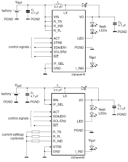
SSL3250A PHOTO FLASH LED DRIVER ELECTRONIC DIAGRAM
These properties caused this device has long battery life and low power strain. Another features that this device has are protecting the battery and LED from overloading, trouble free operation such as overtemperature, over voltage, time-out function, undervoltage lockout, and feedback shorted protection.
Wednesday, October 2, 2013
Simple Battery Discharger Using Discrete Components
The battery discharger published in this website may be improved by adding a Schottky diode (D3). This ensures that a NiCd cell is discharged not to 0.6–0.7 V, but to just under 1 V as recommended by the manufacturers. An additional effect is then that light-emitting diode D2 flashes when the battery connected to the terminals is flat. The circuit in the diagram is based on an astable multivibrator operating at a frequency of about 25 kHz. When transistor T2 conducts, a current flows through inductor L1, whereupon energy is stored in the resulting electromagnetic field. When T2 is cut off, the field collapses, whereupon a counter-emf is produced at a level that exceeds the forward voltage (about 1.6 V) of D2. A current then flows through the diode so that this lights. Diode D1 prevents the current flowing through R4 and C2. This process is halted only when the battery voltage no longer provides a sufficient base potential for the transistors. In the original circuit, this happened at about 0.65 V. The addition of the forward bias of D3 (about 0.3 V), the final discharge voltage of the battery is raised to 0.9–1.0 V. Additional resistors R5 and R6 ensure that sufficient current flows through D3. When the battery is discharged to the recommended level, it must be removed from the discharger since, in contrast to the original circuit, a small current continues to flow through D3, R2-R3, and R5-R6 until the battery is totally discharged.
The flashing of D2 when the battery is nearing recommended discharge is caused by the increasing internal resistance of the battery lowering the terminal voltage to below the threshold level. If no current flows, the internal resistance is of no consequence since the terminal voltage rises to the threshold voltage by taking some energy from the battery. When the discharge is complete to the recommended level, the LED goes out. It should therefore be noted that the battery is discharged sufficiently when the LED begins to flash.


