Friday, December 27, 2013

Simple Op Amp Radio

This is basically a crystal radio with an audio amplifier which is fairly sensitive and receives several strong stations in the Los Angeles area with a minimal 15 foot antenna. Longer antennas will provide a stronger signal but the selectivity will be worse and strong stations may be heard in the background of weaker ones.

Using a long wire antenna, the selectivity can be improved by connecting it to one of the taps on the coil instead of the junction of the capacitor and coil. Some connection to ground is required but I found that standing outside on a concrete slab and just allowing the long headphone leads to lay on the concrete was sufficient to listen to the local news station (KNX 1070).

Simple Op-Amp Radio Circuit Diagram
 The inductor was wound with 200 turns of #28 enameled copper wire on a 7/8 diameter, 4 inch length of PVC pipe, which yields about 220 uH. The inductor was wound with taps every 20 turns so the diode and antenna connections could be selected for best results which turned out to be 60 turns from the antenna end for the diode.

The diode should be a germanium (1N34A type) for best results, but silicon diodes will also work if the signal is strong enough. The carrier frequency is removed from the rectified signal at the cathode of the diode by the 300 pF cap and the audio frequency is passed by the 0.1uF capacitor to the non-inverting input of the first op-amp which functions as a high impedance buffer stage.

The second op-amp stage increases the voltage level about 50 times and is DC coupled to the first through the 10K resistor. If the pairs of 100K and 1 Meg resistors are not close in value (1%) you may need to either use closer matched values or add a capacitor in series with the 10K resistor to keep the DC voltage at the transistor emitter between 3 and 6 volts.

Another approach would be to reduce the overall gain with a smaller feedback resistor (470K). High impedance headphones will probably work best, but walkman stereo type headphones will also work. Circuit draws about 10 mA from a 9 volt source. Germanium diodes (1N34A) types are available from Radio Shack, #276-1123.

Wednesday, December 25, 2013

Infrared Remote Control

This circuit will allow you to turn on any piece of equipment that operates on 115 volts ac. The receiver circuit is based on the Radio Shack infrared receiver module (MOD), part number 276-137. It is also available from some of the other sources listed on my Links page. The MOD accepts a 40khz IR signal that is modulated at 4 khz. When a signal is received the MOD will go low. The sensitivity of the MOD is set by different values for R1 and C1.

Infrared Remote Control Circuit Diagram

The values for R1 may need to be as high as 10,000 ohms and for C1 40uf. This will prevent the unit from turning on under normal lighting conditions. You will need to experiment with the values that work best for you. The output of the 4013 chip a flip flop toggles on and off with the reception of a IR pulse. The output of the 4013 turns on the MOC optical coupler which in turn switches on the triac and supplies power to the AC load.

Monday, December 23, 2013

Garage Stop Light

A novel use of solar cells makes positioning your car in the garage rather easier than old tyres, a mirror, or a chalk mark. The six solar cells in figure 1 serve as power supply and as proximity sensor. They are commercially available at relative low cost. The voltage developed across potentiometer Pi is mainly dependent on the intensity of the light falling onto the cells. The circuit is only actuated when the main beam of one of the cars headlights shines direct onto the cells from a distance of about 200 mm (8 inches). The distance can be varied somewhat with P,

Simple Garage Stop Light Circuit Diagram :

Simple-Garage-Stop-Light-Circuit Diagram

Under those conditions, the voltage developed across C1 is about 3 V, which is sufficient to trigger relaxation oscillator Ni. The BC547B is then switched on via buffer N2 so that D3 begins to  lfash. Diodes Di and D2 provide an additional in- crease in the threshold of the circuit. The total voltage drop of 1.2 V across them ensures that the  potential at pin I of the 4093 is always 1.2 V below the voltage developed by the solar cells. As the trip  level of Ni lies at about 50 per cent of the supply  voltage, the oscillator will only start when the supply voltage is higher than 2.4 V.

The circuit, including the solar cells, is best constructed on a small veroboard as shown in figure 3, and then fitted in a translucent or transparent man- made fibre case. The case is fitted onto the garage wall in a position where one of the cars headlights shines direct onto it. The LED is fitted onto the same wall, but a little higher so that it is in easy view of the driver of the car. When you drive into the garage, you must, of course, remember to switch on the main beam of your headlights!

Source : www.ecircuitslab.com

Saturday, December 21, 2013

Small Power Amplifier 8W 8Ω with TDA 2030

Although the TDA2030 can deliver 20 watts of output power, I deliberately reduced the output power to about 8 watts to supply 10 watt speakers. Input sensitivity is 200mV. Higher input levels naturally will give greater output, but no distortion should be heard. the gain is set by the 47k and 1.5k resistors. The TDA2030 IC is affordable and makes a good replacement amplifier for low to medium audio power systems. Incidentally, it is speaker efficiency that determines how "loud" your music is.

Small Power Amplifier Circuit diagram:

Mini-power_amplifier_8w-Circuit diagram

Parts:

R1-2=47ohmK 1/4W        
R3= 1.5Kohm 1/4W         
R4=1.2ohm /1W        
C1-5=1uF/25V
C2-6=100uF/25V
C3-7=100nF/63V
C4=220nF/63V
D1-2=1N4001
IC1=TDA 2030

Thursday, December 19, 2013

The worker can simply press the pagedown button of cell phone jammer

The worker can simply press the pagedown button of cell phone jammer .
Promise as a wireless presenter products use 2.4G ISM band. The bands product, if less than 1 mW transmit power, is not obtained "Radio Transmission Equipment Type Approval Certificate (SRRC)" The. ISM band that is industrial, scientific and medical band. Generally speaking, countries around the world to retain some of the wireless spectrum to be used for industrial, scientific and medical applications of microwave. No permit application of these bands, just to comply with certain transmission power (typically less than 1W), and do not cause interference to other bands can. ISM band regulations in each country are not uniform. In the United States there are three bands 902-928 MHz ,2400-2484 .5 MHz and 5725-5850 MHz, while in Europe there is part of the 900MHz band is used for GSM communication. The 2.4GHz ISM band common for countries, promise for the 2.4G wireless presenter products are in this band, so no need to obtain permission. cell phone jammer can help achieve the free presentation of the electronic document.
Demonstrator for wireless products promise the maximum transmit power of 1mW, the radiation is very weak. Our products work only when the maximum radiated power equivalent to a normal GSM mobile calls when the maximum radiated power of 1 / 700. So it will not cause injury. Since our products are used for one-code technology, the receiver only receives a corresponding address code transmitter. Both products have frequency hopping, when a serious band interference, it will automatically jump to another frequency band, so using both sets of products will not interfere with each other. Radio Frequency RF is an abbreviation, is the radio frequency technology. Wireless local area network WLAN and mobile phones using radio frequency technology. cell phone jammer can effectively manipulate the turning over of the multimedia.
Wireless Presenter products in technology, and RF is the corresponding infrared technology, called IR. Computers and air conditioning remote control using infrared IR remote control technology. Products using infrared technology direction, the transmitter must align the receiver, and no intervening obstructions. Distance is not more than 7 meters from electromagnetic interference, the advantages of infrared products is the product of low cost, cheap. cell phone jammer can make it very convenient to make speeches.
Using radio frequency technology products are used radio waves to transmit control signals, and its directional characteristics, can not "face to face" control, distance, up to tens of meters.

Tuesday, December 17, 2013

Electronic Security System

This reliable and easy-to-operate electronic security system can be used in banks, factories, commercial establishments, houses, etc. The system comprises a monitoring system and several sensing zones. Each sensing zone is provided with a closed-loop switch known as sense switch. Sense switches are fixed onthedoors of premises under security and connected to the monitoring system. As long as the doors are closed, sense switches are also closed. The monitoring system can be installed at a convenient central place for easy operation.

Fig. 1 shows the monitoring circuit only for zone 1 along with the common alarm circuit. For other zones, the monitoring circuit is identical, with only the prefixes of components changing as per zone number. Encircled points A, B, and C of each zone monitoring circuit need to be joined to the corresponding points of the alarm circuit (upper half of Fig. 1).

Fig. 1: Monitoring Circuit Along with the Alarm Circuit diagram

Monitoring circuit along with the alarm circuit

When zone 1 sensing switch S11, zone switch S1 are all on, pnp transistor T12 reverse biases to go in cut-off condition, with its collector at around 0 volt. When the door fitted with sensor switch S11 is opened, transistor T12 gets forward biased and it conducts. Its collector voltage goes high, which forward biases transistor T10 via resistor R10 to turn it on. (Capacitor C10 serves as a filter capacitor.) As a result, the collector voltage of transistor T10 falls to forward bias transistor T11, which conducts and its collector voltage is sustained at a high level. Under this latched condition, sensor switch S11 and the state of transistor T12 have no effect. In this state, red LED11 of the zone remains lit.

Simultaneously, the high-level voltage from the collector of transistor T11 via diode D10 is applied to VDD pin 5 of siren sound generator IC1 (UM3561) whose pin 2 is grounded. Resistor R3 connected across pins 7 and 8 of IC1 determines the frequency of the in-built oscillator. As a result, IC1 starts generating the audio signal output at pin 3. The output voltage from IC1 is further amplified by Darlington pair of transistors T1 and T2. The amplified output of the Darlington pair drives the loudspeaker whose output volume can be controlled by potentiometer VR1. Capacitor C1 serves as a filter capacitor.

Fig. 2: Physical Layout of Sensors and Monitoring Alarm System:

Physical layout of sensors and monitoring alarm system

You can alter the alarm sound as desired by changing the connections of IC1 as shown in the table.

F99_table

The circuit continues to sound the alarm until zone door is closed (to close switch S11) and the reset switch is pressed momentarily (which causes transistor T10 to cut off, returning the circuit to its initial state). The system operates off a 3V DC battery or recharging battery with charging circuit or battery eliminator. If desired, more operating zones can be added. Initially keep the monitoring system switch S1 off. Keep all the zone doors fixed with sensing switches S11, S21, S31, S41, etc closed. This keeps the sensing switches for respective zones in closed position. Also keep zone slide switches S12, S22, S32, S42, etc in ‘on’ position.

This puts the system in operation, guarding all the zone doors.Now, if the door of a particular zone is opened, the monitoring system sounds an audible alarm and the LED corresponding to the zone glows to indicate that the door of the zone is open. The alarm and the LED indication will continue even after that particular door with the sensing switch is immediately closed, or even if that switch is removed/damaged or connecting wire is cut open. Any particular zone in the monitoring system can be put to operation or out of operation by switching on or switching off the corresponding slide switch in the monitoring system.

Source : http://www.ecircuitslab.com/2012/05/electronic-security-system.html

Tuesday, October 8, 2013

Zero Gain Mod For Non Inverting Opamp

Electronics textbooks will tell you that a non-inverting opamp normally cannot be regulated down to 0 dB gain. If zero output is needed then it is usual to employ an inverting amplifier and a buffer amp in front of it, the buffer acting as an impedance step-up device. The circuit shown here is a trick to make a non-inverting amplifier go down all the way to zero output. The secret is a linear-law stereo potentiometer connected such that when the spindle is turned clockwise the resistance in P1a increases (gain goes up), while the wiper of P1b moves towards the opamp output (more signal). When the wiper is turned anti-clockwise, the resistance of P1a drops, lowering the gain, while P1b also supplies a smaller signal to the load. In this way, the output signal can be made to go down to zero.

Sunday, October 6, 2013

6 Channel Running Light

The circuit of the running light comprises two integrated circuits (ICs), a resistor, a capacitor and seven light-emitting diodes (LEDs), Decade scaler IC2 ensures that the LEDs light sequentially. The rate at which this happens is determined by the clock at pin 14. The clock is generated by IC1, which is arranged as an astable multivibrator. Its frequency is determined by R1-C1. The touch switch, consisting of two small metal disks is optional. When switch S1 is in position ‘off’, the circuit may be actuated by the touch switch. By the way, this enables the circuit to be used as an electronic die (in which case the LEDs have to be numbered from 1 to 6). The running light is powered by a 9 V battery or mains adapter. It draws a current not exceeding 20 mA.

6-Channel Running Light

Friday, October 4, 2013

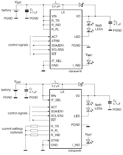
SSL3250A PHOTO FLASH LED DRIVER ELECTRONIC DIAGRAM

SSL3250A PHOTO FLASH LED DRIVER ELECTRONIC DIAGRAM

These properties caused this device has long battery life and low power strain. Another features that this device has are protecting the battery and LED from overloading, trouble free operation such as overtemperature, over voltage, time-out function, undervoltage lockout, and feedback shorted protection.

Wednesday, October 2, 2013

Simple Battery Discharger Using Discrete Components

The battery discharger published in this website may be improved by adding a Schottky diode (D3). This ensures that a NiCd cell is discharged not to 0.6–0.7 V, but to just under 1 V as recommended by the manufacturers. An additional effect is then that light-emitting diode D2 flashes when the battery connected to the terminals is flat. The circuit in the diagram is based on an astable multivibrator operating at a frequency of about 25 kHz. When transistor T2 conducts, a current flows through inductor L1, whereupon energy is stored in the resulting electromagnetic field. When T2 is cut off, the field collapses, whereupon a counter-emf is produced at a level that exceeds the forward voltage (about 1.6 V) of D2.

Simple Battery Discharger Using Discrete ComponentsA current then flows through the diode so that this lights. Diode D1 prevents the current flowing through R4 and C2. This process is halted only when the battery voltage no longer provides a sufficient base potential for the transistors. In the original circuit, this happened at about 0.65 V. The addition of the forward bias of D3 (about 0.3 V), the final discharge voltage of the battery is raised to 0.9–1.0 V. Additional resistors R5 and R6 ensure that sufficient current flows through D3. When the battery is discharged to the recommended level, it must be removed from the discharger since, in contrast to the original circuit, a small current continues to flow through D3, R2-R3, and R5-R6 until the battery is totally discharged.

The flashing of D2 when the battery is nearing recommended discharge is caused by the increasing internal resistance of the battery lowering the terminal voltage to below the threshold level. If no current flows, the internal resistance is of no consequence since the terminal voltage rises to the threshold voltage by taking some energy from the battery. When the discharge is complete to the recommended level, the LED goes out. It should therefore be noted that the battery is discharged sufficiently when the LED begins to flash.

Monday, September 30, 2013

Serial To Parallel Converter

This converter may help if just the serial port on a personal computer is free, whereas the printer needs a parallel (Centronics) port. It converts a serial 2400 baud signal into a parallel signal. The TxD line, pin 3, CTS line, pin 8 and the DSR line, pin 6, of the serial port are used - see diagram. The CTS and DSR signals enable handshaking to be implemented. Since the computer needs real RS232 levels, an adaptation from TTL to RS232 is provided in the converter by a MAX232. This is an integrated level converter that transforms the single +5V supply into a symmetrical ±12V one.

Serial To Parallel Converter circuit diagramThe serial-to-parallel conversion is effected by IC1. This is essentially a programmed PIC controller that produces a Centronics compatible signal from a 2400 baud serial signal (eight data bits, no parity, one stop bit). The IC also generates the requisite control signals. If there is a delay on the Centronics port, the RS232 bitstream from the computer may be stopped via the Flow signal (pin 17). This ensures that no data is lost. The controller needs a 4 MHz ceramic resonator, X1.

Thursday, September 26, 2013

Simple Battery Isolator

This circuit is even simpler and employs a 6V feed from one of the stator connections on the vehicle’s alternator. This is connected to a 6V automotive relay (RLY1) which controls a Continuous Duty Solenoid (RLY2). This solenoid electrically connects or isolates the batteries. When the engine is started and the alternator stator voltage rises, the 6V relay turns on. This turns on the Continuous Duty Solenoid to connect the two batteries in parallel. As long as the engine is running, the vehicle’s alternator will maintain charge in both batteries.

When the engine is shut down, the alternator stator voltage drops and the Continuous Duty Solenoid switches off, thus isolating the second battery from the vehicle’s electrical system. Provided that camping accessories are only connected to the second battery, the main battery should never discharge. Because the concept is entirely dependent upon the alternator’s stator output voltage, you cannot forget to turn the system on or off as it happens automatically.

Tuesday, September 24, 2013

AUTOMATIC AIRFLOW DETECTOR ELECTRONIC DIAGRAM


AUTOMATIC AIRFLOW DETECTOR ELECTRONIC DIAGRAM

Sensor used in this circuit is a bulb filament. If there is no airflow, the filament resistance would give low value. On the other hand, if there is airflow, the filament resistance would varies. The variation of the resistance is caused by the heat difference between filament. It also effects to the voltage variation passing through that filament. That voltage difference will be processed by LM339 op-amp and displayed by the LED.

Parts list :


  •     LED1 : LED 5mm
  •     IC1 volt regulator : LM7805
  •     Polar Capacitor C1 : 47 uF/15V
  •     Resistor R1 : 100 ohm
  •     Resistor R2 : 470 ohm
  •     Resistor R3 : 10k ohm
  •     Potensiometer R4 : 100k ohm
  •     Resistor R5 : 1k ohm
  •     IC2 op-amp : LM339
  •     Bulb filament
  •     Power supply/battery 12V


Sunday, September 22, 2013

Loudspeaker Protector Monitors Current

This circuit uses a 0.1O 1W resistor connected in series with the output of a power amplifier. When the amplifier is delivering 100W into an 8O load, the resistor will be dissipating 1.25W. The resulting temperature rise is sensed by a thermistor which is thermally bonded to the resistor. The thermistor is connected in series with a resistor string which is monitored by the non-inverting (+) inputs of four comparators in an LM339 quad comparator. All of the comparator inverting inputs are connected to an adjustable threshold voltage provided by trimpot VR1. As the thermistor heats up, its resistance increases, raising the voltage along the resistor ladder.

Loudspeaker protector monitors current circuit schematic

When the voltage on the non-inverting input of each comparator exceeds the voltage at its inverting input, the output switches high and illuminates the relevant LED. NOR gate latches are connected to the outputs of the third and fourth comparators. When the third comparator switches high, the first latch is set, turning on Q1 and relay 1. This switches in an attenuation network (resistors RA & RB) to reduce the power level. However, if the power level is still excessive, comparator 4 will switch, setting its latch and turning on Q2 and relay 2.

This disconnects the loudspeaker load. The thermistor then needs to cool down before normal operation will be restored. The values of R1-R4 depend on the thermistor used. For example, if a thermistor with a resistance of 1.5kO at 25°C is used, then R1 could be around 1.5kO and R2, R3 and R4 would each be 100O (depending the temperature coefficient of the thermistor). The setup procedure involves connecting a sinewave oscillator to the input of the power amplifier and using a dummy load for the output. Set the power level desired and adjust trimpot VR1 to light LED1. Then increase the power to check that the other LEDs light at satisfactory levels.

Friday, September 20, 2013

Fuse Box BMW 328i Central 1999 Diagram

Fuse Box BMW 328i Central 1999 Diagram - Here are new post for Fuse Box BMW 328i Central 1999 Diagram.

Fuse Box BMW 328i Central 1999 Diagram


Fuse Box BMW 328i Central 1999 Diagram

Fuse Panel Layout Diagram Parts: ABS system, adjustment driver seat, adjusment passenger seat, air bag, air conditioner, blower, brake light, central locking system, cigar lighter, electric fan, electric seat heating, engine control, folding outside mirror, fog light, garage door opener, heated outside mirror, heated rear window, heated spray nozzle, horn, immobilizer, instrument cluster.

Thursday, September 12, 2013

Kawasaki KLR 250 Carb Cleaning Information

Bottom View of the KLR 250 CVK34 carburetor showing the main and pilot jetsIf you were to browse any KLR250 related forum the most common ailment youd hear owners complain about is some type of starting or running problem, usually carburetor related. These problems arent biased to just the KLR, any carbureted bike can experience them. Theyre usually due to dirt in the fuel clogging a jet, or varish gumming everything up. The only solution is to remove the carb from the bike and give it a thorough cleaning and inspection. Thats what this article is meant to do, show you the basics of the KLR250 carburetor and give a quick run through on how to clean it.We wont get into how a carb works, but if youre interested in learning more check out The Care and Feeding of the Keihn Carb.

Kawasaki KLR 250 carburetor diagram cvk34The KLR 250 comes with a Keihn CVK34 carburetor. Dont let the parts diagram to the left fool you, CVK34 is a very simple design. To clean the carb youll need to remove it from the bike. Probably one of the more painful processes whenever you have to work on your bikes carb is trying to get it out of the bike. At the very least itll require removing the side plastics, seat, and fuel tank, though we have found that unbolting the exhaust muffler and the top bolts of the subframe (the part the seat bolts to) make things easier by allowing you to pivot the entire subframe backwards giving better access to the carb. Once youve gotten to the carb follow these steps to disconnect and remove it.

Removal:
1. Turn off the fuel petcock on the fuel tank
2. Place a container under the fuel drain hose. That is the hose which leads from the fuel drain screw to just in front of the rear wheel.
3. Open drain screw, located on the bottom right side of the carb (on the float bowl) and allow all of the fuel to drain from the carb.
4. Remove the fuel line from the left side of the carb (black rubber line from the fuel tank)
5. Remove the throttle cables, one screw holds the bracket in place.
6. Carefully unscrew the plastic choke cable nut from the left side of the carburetor. This is where the choke cable screws into the carb. The plastic nut is very fragile so be careful!
7. Loosen the clamp on the front side of the carb holding it to the engine.
8. Remove the rear carb to airbox tube

OK now you should have the carb out of the bike and holding it in your hands. Next step is tearing it down while being very careful not to lose or damage anything in the process.

KLR 250 Carburetor Picture PhotoTeardown:
1. Remove the four screws on the plastic piece on the top of the carb. Underneath there should be a diaphragm, spring, slide, needle and white piece of plastic. Make a mental note of the order of those parts (slide, needle, white plastic piece, spring) and remove them. Be careful not to tear the rubber diaphragm.
2. Remove the float bowl. That is the metal bowl on the bottom of the carb, held in place with four screws. Be careful when removing it as the float and needle valve can fall out. Make a note of the position of the float and needle and remove them.
3. Next step is to unscrew the main and pilot jets from the carb body. (see diagram above for their location)

Pilot Screw Info:
The KLRs carb has a pilot mixture screw which controls the amount of fuel that enters the engine while at idle. However to stop owners from fiddling with it Kawasaki covered the screw with a small tin cap. The only way to get to this screw is to carefully drill a small hole in the tin cap and then pry it off with a small screw driver. The utmost care must be taken so you dont screw all of the way through to the pilot screw itself. Once the screw is accessible then you can remove it. There should be an o-ring, washer, and spring on the end of it, note their order and set them to the side.

Cleaning:
Thats about all you need to disassemble. Wasnt that hard was it? Now its time to clean everything. Just about everyone has their own way of doing this but what we suggest is buying a few bottles of carb cleaner (the kind you pour in your cars fuel tank) and a couple cans of spray type carb cleaner that have the small plastic tubes on them. Fill a small container with the carb cleaner (bottle type) and soak all of the metal parts in it, including the carburetor body. Note: Do not use either carb cleaner on any plastic or rubber parts, itll eat them. What youre trying to accomplish is the removal of all varnish from inside the carb body, and jets. After theyve soaked for a couple of hours its time to spray out all of the small passages in the carb body, and the tiny holes in jets with the spray type carb cleaner and then follow it up with a blast of compressed air. Youre trying to make sure there is nothing clogging up those small holes, you leave one grain of sand behind and youll be doing this again so be diligent! By this point you should have a sparkling clean carburetor, all that is left to do is reassemble everything.

Reassembly:
There isnt much to say here, just reassemble everything in the reverse order you took it apart. When the time comes to re-install the pilot screw make sure the o-ring, washer, and spring are in place and screw it in all of the way and back out two full turns. (further adjustment may be needed but this is a good starting point) When you re-install the slide components be careful not to pinch or tear the rubber diaphragm.

Float Adjustment:
While you have the carb apart and cleaned this is the perfect time to check the float height adjustment. Simply install the float and needle valve onto the carb body and hold it as shown in the diagram to the left. You want the needle to be lying on its seat but not pushed down. To check for proper adjustment measure from the float bowl mating surface, and the top of the float. (4) The adjustment should be 17mm. If you find its not 17mm then you correct it by ever so slightly bending the float bowl tang with a pair of needle nose pliers. (see arrow in this picture) Small adjustment result in big changes in the float height, so go easy. Once youve got it to 17mm youre all set.

Thats it! Now re-install the carb back in the bike and youre good to go!

Image Sources: Gadjetjq.com - KLR650.net - Kawasaki.com
Note: The top image is of a CVK40. While it is a different carburetor than the CVK34 in the KLR 250 their layouts are almost identical.

Tuesday, September 10, 2013

Digital Electronic Lock Circuit Diagram

This Digital Electronic Lock Circuit Diagram shown below uses 4 common logic ICs to allow controlling a relay by entering a 4 digit number on a keypad. The first 4 outputs from the CD4017 decade counter (pins 3,2,4,7) are gated together with 4 digits from a keypad so that as the keys are depressed in the correct order, the counter will advance. As each correct key is pressed, a low level appears at the output of the dual NAND gate producing a high level at the output of the 8 input NAND at pin 13.

Read : Cheap Bicycle Alarm Schematics Circuit

Digital Electronic Lock Circuit Diagram

Digital Electronic Lock Circuit Diagram

The momentary high level from pin 13 activates a one shot circuit which applies an approximate 80 millisecond positive going pulse to the clock line (pin 14) of the decade counter which advances it one count on the rising edge.

Read : Emergency Light and Alarm Circuit Diagram

A second monostable, one shot circuit is used to generate an approximate 40 millisecond positive going pulse which is applied to the common point of the keypad so that the appropriate NAND gate will see two logic high levels when the correct key is pressed (one from the counter and the other from the key). The inverted clock pulse (negative going) at pin 12 of the 74C14 and the positive going keypad pulse at pin 6 are gated together using two diodes as an AND gate (shown in lower right corner).

Read : Burglar Alarm With Timed Shutoff Circuit Diagram

The output at the junction of the diodes will be positive in the event a wrong key is pressed and will reset the counter. When a correct key is pressed, outputs will be present from both monostable circuits (clock and keypad) causing the reset line to remain low and allowing the counter to advance. However, since the keypad pulse begins slightly before the clock, a 0.1uF capacitor is connected to the reset line to delay the reset until the inverted clock arrives.

Read : 5 Zone alarm Circuit Diagram

The values are not critical and various other timing schemes could be used but the clock signal should be slightly longer than the keypad pulse so that the clock signal can mask out the keypad and avoid resetting the counter in the event the clock pulse ends before the keypad pulse. The fifth output of the counter is on pin 10, so that after four correct key entries have been made, pin 10 will move to a high level and can be used to activate a relay, illuminate an LED, ect. At this point, the lock can be reset simply by pressing any key. The circuit can be extended with additional gates (one more CD4011) to accept up to a 8 digit code.

Read :  Alarm Control Keypad Circuit Diagram

The 4017 counting order is 3 2 4 7 10 1 5 6 9 11 so that the first 8 outputs are connected to the NAND gates and pin 9 would be used to drive the relay or light. The 4 additional NAND gate outputs would connect to the 4 remaining inputs of the CD4068 (pins 9,10,11,12). The circuit will operate from 3 to 12 volts on 4000 series CMOS but only 6 volts or less if 74HC parts are used. The circuit draws very little current (about 165 microamps) so it could be powered for several months on 4 AA batteries assuming only intermittent use of the relay.

Wednesday, September 4, 2013

00 To 99 Minute Timer Using PIC16F628A Microcontroller

his might be a good practice project for beginners who just started learning embedded electronics. It is about making a very basic programmable digital timer using a PIC16F628A microcontroller. The timer duration can be set from 0-99 minutes.

As I mentioned earlier, the microcontroller used in this project is PIC16F628A running at 4.0 MHz clock using an external crystal. An HD44780 based 16×2 character LCD is the main display unit of the project where you can watch and set the timer duration using tact switch inputs. There are three tact switches connected to RB0 (Start/Stop), RB1 (Unit), and RB2 (Ten) pins. You can select the timer interval from 0-99 min using Unit and Ten minute switches. The Start/Stop switch is for toggling the timer ON and OFF. When the timer gets ON, a logic high signal appears on the RA3 pin, which can be used to switch on a Relay. The circuit diagram of this project is described below.


When the device is powered ON, the microcontroller initializes the LCD display and shows the following message. The timer is initially OFF and so does the LED or relay, whichever is connected to RA3 pin. You can set time duration between 00-99 min (in step of 1 min) using the Unit and Ten tact switches. Each switch press will increment the corresponding time digit.

When the desired time is set, press the Start/Stop switch to turn ON the timer. The RA3 pin goes high (LED glows) and the count down begins. When the timer is ON, the remaining time is also shown on the LCD screen. When the time elapsed, the timer stops and the LED turns OFF. You can interrupt and stop the timer at anytime by pressing the Start/Stop switch once more. The firmware for PIC is developed using mikroC Pro for PIC compiler. The use of Timers are avoided for simplicity. The time delays are created using the Delay_ms() function of mikroC, which seems to give reasonably accurate timing delays.

Download Mikroc Source Code And HEX File


Monday, September 2, 2013

Metal Detector Schematic Using CS209A

A very simple metal detector electronic project circuit can be designed using the CS209A integrated circuit manufactured by Cherry Semiconductor.The CS209A integrated circuit is a bipolar monolithic integrated circuit for use in metal detection proximity sensing applications.The CS209A metal detector contains two on-chip current regulators, oscillator and low-level feedback circuitry, peak detection/demodulation circuit, a comparator and two complementary output stages.The oscillator, along with an external LC network, provides controlled oscillations where amplitude is highly dependent on the Q of the LC tank.

Metal Detector Schematic Circuit Diagram


The detector, is a single 100uH coil. The IC has an integral oscillator the choke forms part of an external LC circuit, its inductance being changed by the proximity of metal objects. It is the change in oscillation that is amplified and demodulated. Led 1 will light and the buzzer will sound when the inductance its changed. Set up is easy : R5 is adjusted with the LC away from any metal source so that the LED lights and buzzer sounds. The control is backed off so that the LED goes out and buzzer stops. When the choke comes into contact with any metal object that alters its inductance, LED 1 and the buzzer will activate.

FOr this electronic project youll need the following electronic parts: R1=220ohms, R2,R5=10k,R3=1k ,C1,C3=2.2nF; C2=10uF. Entire circuit can be powered from a 9 volts battery.

Saturday, August 31, 2013

AM Receiver Circuit

Description:
This is a compact three transistor, regenerative receiver with fixed feedback. It is similar in principle to the ZN414 radio IC which is now no longer available. The design is simple and sensitivity and selectivity of the receiver are good.
Circuit Diagram

Notes:
All general purpose transistors should work in this circuit, I used three BC109C transistors in my prototype.The tuned circuit is designed for medium wave. I used a ferrite rod and tuning capacitor from an old radio which tuned from approximately 550 - 1600kHz. Q1 and Q2 form a compund transistor pair featuring high gain and very high input impedance. This is necessary so as not to unduly load the tank circuit.
The 120k resistor provides regenerative feedback,between Q2 output and the tank circuit input and its value affects the overall performance of the whole circuit. Too much feedback and the circuit will become unstable producing a "howling sound". Insufficient feedback and the receiver becomes "deaf". If the circuit oscillates,then R1s value may be decreased; try 68k. If there is a lack of sensitivity, then try increasing R1 to around 150k. R1 could also be replaced by a fixed resisor say 33k and a preset resistor of 100k. This will give adjustment of sensitivity and selectivity of the receiver.
Transistor Q3 has a dual purpose; it performs demodulation of the RF carrier whilst at the same time, amplifying the audio signal. Audio level varies on the strength of the received station but I had typically 10-40 mV. This will directly drive high impedance headphones or can be fed into a suitable amplifier.
Construction:
All connections should be short, a veroboard or tagstrip layout are suitable. The tuning capacitor has fixed and moving plates. The moving plates should be connected to the "cold" end of the tank circuit, this is the base of Q1, and the fixed plates to the "hot end" of the coil, the juction of R1 and C1. If connections on the capacitor are reversed, then moving your hand near the capacitor will cause unwanted stability and oscillation.
Finally here are some voltagee checks from my breadboard prototype.This should help in determining a working circuit:-
All measurements made with a fresh 9volt battery and three BC109C transistors with respect to the battery negative terminal.
Parts
Q1 (b) 1.31V
Q2 (b) 0.71V
Q2 (c) 1.34V
Q3 (b) 0.62V
Q3 (c) 3.87V

Author: Andy Collinson
Source: http://www.zen22142.zen.co.uk

Thursday, August 15, 2013

Simple AC Power Current detector Circuit with LM1458

This circuit will detect power line currents of 250 mA or more without making electrical connections to the line. Current is detected by passing a line of alternating current through an inductive pickup (L1) as a screen diameter of 1 inch U-bolt wound with 800 turns # 30 – # 35 magnet wire.

The pickup could be made from rings of iron or other type of processor core that allows enough space to pass one of the AC lines through the center. Only one of the power line is the line or neutral must come from the center of the pickup to avoid the fields cancel.

Simple AC Power Current detector Circuit with LM1458

I tested the circuit with a 2 wire extension cord that had separated the twin wires a small distance with an exacto knife to allow the U-bolt to encircle a single cable. The magnetic pick-up (U-bolt) produces about 4 millivolts peak for a series of alternating current of 250 mA, or AC load of around 30 watt

The signal from the pickup has grown about 200 times the output of pin op-amp 7, followed by the peak detected by diode and capacitor connected to pin 7. The second op-amp used as a reference point, which detects voltage increases above the drop pass.

The minimum mark required to cause the comparator output stage is a positive change of 800 mV peak around a power line 30-watt. The 1458 swing op-amp output in just a couple of times the ground so a voltage divider (1K/470) is used to reduce the voltage signal at about 0,7 volt.

An additional diode added in series with transistor base to ensure that off when the voltage op-amp is 2 volts. You can get a piece “of relay chatter if the AC load is close to the switching point so a larger load 50 W or higher recommended. The sensitivity can be increased by adding more becomes a pick-up

Tuesday, August 13, 2013

Simple 500W Audio Power Amplifier Circuit Diagram with Transistor

We take transistor MJL2194 and MJL2193 for drive output signal.so the amp has a capacity for enormous instantaneous current ability.

 Simple 500W Audio Power Amplifier Circuit Diagram with Transistor

I think, it is useful for you to apply the circuit with your sound devices.

Circuit Functional
I use the -85 volt when the output current is supplied to the drive 350 to 340 very hot. Increase the output current, but it was too cold. The output to heat up faster than a normal open it. Sounds obvious, but sound quality is quite good.

I recomment it by turning out for the evening. If the drive is mounted on the metal part out.

I think simple. View full above, the observation that R 30 ohm then the voltage across the 0.86 V show that the new through its 29 mA if you add a file to / – 85 V, and suppose that the voltage across the component body. It was the same in both the R 30 ohm to get a very light 5 0.86 = 5.86 V and the current I will be 5.86/30 = 0.195 A = 195 mA, and the specification of mje340. mje350 get Ic (max) = 500 mA, so it is natural for it to heat up. Actually, it is not necessary to adhere to sync tr output should be interested in the following two tr power drive is better. For VR should be R300 .

Sunday, August 11, 2013

12V Speed Controller Dimmer

This handy circuit can be utilized as a velocity regulateler for a 12V motor rated up to 5A (continuous) or as a dimmer for a 12V halogen or usual incandescent lamp rated up to 50W. It varies the facility to the weight (motor or lamp) the usage of pulse width modulation (PWM) at a pulse frequency of around 220Hz.  SILICON CHIP has produced quite a few DC speed regulatelers through the 12 monthss, the most latest being our high-power 24V 40A design featured in the March & April 2008 considerations. Another very popular design is our 12V/24V 20A design featured in the June 1997 issue and we've also featured plenty of reversible 12V designs.
 
Project Image :
 12V Speed Controller/Dimmer Project Image

For many utilitys although, a lot of these designs are over-kill and a much more effective circuit will suffice. Which is why we are offering this basic design which uses a 7555 timer IC, a Mosfet and no longer much else. Being a easy design, it does no longer screen motor back-EMF to supply superior speed legislation and nor does it have any fancy overload safety aside from a fuse. However, it is a very environment friendly circuit and the equipment cost is somewhat low.

Parts layout:


Connection diagram:


There are many softwares for this circuit with the intention to all be in protecting with 12V motors, lovers or lamps. You can use it in automotives, boats, and recreational vehicles, in variation boats and adaptation railways and so on. Want to keep watch over a 12V fan in a car, automotiveavan or computer? This circuit will do it for you. The circuit makes use of a 7555 timer (IC1) to generate variable width pulses at about 210Hz. This forces Mosfet Q3 (via transistors Q1 & Q2) to control the rate of a motor or to dim an incandescent lamp.

Circuit diagram :
12V Speed Controller/Dimmer Circuit Diagram

While the circuit can dim 12V halogen lamps, we must point out that dimming halogen lamps may be very wasteful. In state of affairss where you need dimmable 12V lamps, you will be a lot better off substituting 12V LED lamps which are now conveniently available in standard bayonet, miniature Edison screw (MES) and MR16 halogen bases. Not simplest are these LED alternative lamps far more efficient than halogen lamps, they do not get any place close to as hot and additionally will last an ideal deal longer.

Source : Silicon Chip

Friday, August 9, 2013

Telephone Call Recorder

Today telephone has become an integral part of our lives. It is the most widely used communication device in the world. Owing to its immense popularity and widespread use, there arises a need for call recording devices, which find application in call centres, stock broking firms, police, offices, homes, etc. Here we are describing a call recorder that uses very few components. But in order to understand its working, one must first have the basic knowledge of standard telephone wiring and a stereo plug.

Telephone Call Recorder Circuit diagram

In India, landline telephones primarily use RJ11 wiring, which has two wires—tip and ring. While tip is the positive wire, ring is the negative one. And together they complete the telephone circuit. In a telephone line,  voltage between tip and ring is around 48V DC when handset is on the cradle(idle line). In order to ring the phone for an incoming call, a 20Hz AC current of around 90V is superimposed over the DC voltage already present in the idle line.  The negative wire from the phone line goes to IN1, while the positive wire goes to IN2. Further, the negative wire from OUT1 and the positive wire from OUT2 are connected to the phone. All the resistors used are 0.25W carbon film resistors and all the capacitors used are rated for 250V or more.
The negative terminal of ‘To AUX IN’ is connected to pin 1 of the stereo jack while the positive terminal is connected to pins 2 and 3 of the stereo jack. This stereo jack, in turn, is connected to the AUX IN of any recording device, such as computer, audio cas-sette player, CD player, DVD player, etc. Here we shall be connecting it to a computer. When a call comes in, around 90V AC current at 20Hz is superimposed over the DC voltage already present in the idle line.
Telephone Call Recorder Mic
This current is converted into DC by the diodes and fed to resistor R1, which reduces its magnitude and feeds it to LED1. The current is further reduced in magnitude by the resistor R2 and fed to the right and left channels of the stereo jack, which are connected to the AUX IN port of a computer.  Any audio recording software, such as AVS audio recorder (available at: http://www.avs4you.com/AVS-Audio-Recorder.aspx), Audacity audio recorder (http://audacity.sourceforge.net/), or audio recorder (http://www.audio-tool.net/audio_recorder_for_free.html), can be used to record the call. When a call comes in, one needs to launch the audio recording software and start recording.
Telephone Call Recorder
For phone recording, simply connect the stereo jack to the AUX IN port of the PC. Install the  Audacity audio recorder (different versions are available for free for different operating systems at http://audacity.sourceforge.net/) on your PC. Run the executable  Audacity file. In the main window, you will find a dropdown box in the top right corner. From this box, select the AUX option. Now you are ready to record any call. As soon as a call comes in, press the record button found in the Audacity main window and then pick up the telephone receiver and answer the call. Press the stop button once the call ends. Now go to the file menu and select the ‘Export as WAV’ option and save the file in a desired location.

You may change the value of resistor R2 if you want to change the output volume. You can use a variable resistor in series with R2 to vary the volume of the output. The recorded audio clip can be edited using different options in the  Audacity software. You can assemble the circuit on a general-purpose PCB and enclose it in a small cabinet. Use an RJ11 connector and stereo jack for connecting the telephone set and computer (for call recording). Telephone cords can be used to connect to the phone line and the circuit. Use of a shielded cable is recommended to reduce disturbances in the recording. These can also be reduced by increasing the value of R2 to about 15 kilo-ohms.
EFY note. Audacity recording software is included in this month’s EFY-CD under ‘Utilities’ section.

Source: http://www.ecircuitslab.com/2011/07/telephone-call-recorder.html

Wednesday, August 7, 2013

1998 Toyota Land Cruiser Electrical Wiring Diagram

1998 Toyota Land Cruiser Electrical Wiring DiagramThis is the Official Repair Manual that the dealers and shops use. This is the finest manual available. It is very detailed with good diagrams, photos and exploded views. A must for anyone who insists on Genuine OEM quality parts.

you can buy this diagram books at here

Monday, August 5, 2013

2005 Toyota 4Runner The Rear Windshield Wiper Is Not Working


My car is the 2005 Toyota 4Runner, and my rear windshield wiper is not working, the cleaning fluid also does not come out on the back windshield. My car is still under warranty but before I call the dealership, does anyone has any suggestion on what the problem might be? I want to try some solutions my self since I learn that if I take my car to the shop and I don’t have to b/c, it cots me something, thanks.
 

Answer: Just check the fuses, if the dealership suspects you for messing with something, they could void the warranty. The rear wipers might use separate fuse from the front, what you need to do is just to make sure that every thing is plug in. You could find the plug near the gate.


Saturday, August 3, 2013

TA7230P TA7236P TA7237AP amplifier schematic

Amplifier circuit here is all based on the ic in the gains. Three IC TA7230P, TA7236P, TA7237AP is intregated circuit (IC) which was applied to the power amplifier. Each IC has a different output, different input voltage, all IC TA7230P, TA7236P, TA7237AP is manufactured by Toshiba.

You can see maximum minimum voltage , power output , and other here
TA7230P, TA7236P, TA7237AP amplifier schematic

Thursday, August 1, 2013

1997 Audi A4 Air Conditioning System Circuit and Schematic Diagram on 1997 Audi A4


The following wiring diagram / scematic shows 1997 Audi A4 air conditioning system Circuit and Schematic Diagram which consists of A/C control head, footwell/defroster, flap motor and sensor, temperature regulator, motronic engine control module, interior temperature fan and sensor, digital outside air temperature/ transmission range selector lever display, sunlight photo sensor, A/C compressor speed sensor, outside temperature sensor, fresh air intake duct, fuse panel and instrument cluster, A/C compressor clutch relay, central flap motor and sensor, back pressure motor and sensor, center outlet temperature sensor, fresh air blower, coolant fan control thermal switch, coolant fan, and coolant fan control relay. 


For detailed information about 1997 Audi A4 Air Conditioning System Circuit and Schematic Diagram here (diagram 1 and diagram 2, source: autolib.diakom.ru)

Tuesday, June 4, 2013

Structured Wiring

Structured Wiring on Structured Wiring Panels Create A Safe Environment For Services To Be
Structured Wiring Panels Create A Safe Environment For Services To Be.


Structured Wiring on Structured Wiring
Structured Wiring.


Structured Wiring on Structured Wiring Design
Structured Wiring Design.


Structured Wiring on Structured Wiring Jpg
Structured Wiring Jpg.


Structured Wiring on Structured Wiring
Structured Wiring.


Structured Wiring on Structured Wiring   Services   Home Audio Video  Home Theater
Structured Wiring Services Home Audio Video Home Theater.


Structured Wiring on Structured Wiring
Structured Wiring.


Structured Wiring on Installs Computer Networking Wiring As Part Of Its Structured Wiring
Installs Computer Networking Wiring As Part Of Its Structured Wiring.


Structured Wiring on Residential Security Structured Wiring   Http   Americanalarms Us
Residential Security Structured Wiring Http Americanalarms Us.


Structured Wiring on Structured Wiring
Structured Wiring.


Sunday, June 2, 2013

Thermostat Wiring Informationprothermostats Programmable

Thermostat Wiring on Air Conditioner Thermostat Wiring
Air Conditioner Thermostat Wiring.


Thermostat Wiring on Thermostat Wiring For Conventional Gas Furnace Air Conditioner Split
Thermostat Wiring For Conventional Gas Furnace Air Conditioner Split.


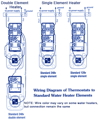
Thermostat Wiring on Typical Electric Water Heater Construction   Wiring Diagram
Typical Electric Water Heater Construction Wiring Diagram.


Thermostat Wiring on Thermostat Wiring Information   Prothermostats Com   Programmable
Thermostat Wiring Information Prothermostats Com Programmable.


Thermostat Wiring on Thermostat Wiring Issues   Doityourself Com Community Forums
Thermostat Wiring Issues Doityourself Com Community Forums.


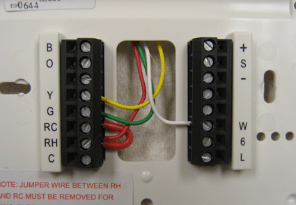
Thermostat Wiring on Honeywell Digital Thermostat Wiring Diagram
Honeywell Digital Thermostat Wiring Diagram.


Thermostat Wiring on Of Thermostat Required For These More Complex Systems From The Wiring
Of Thermostat Required For These More Complex Systems From The Wiring.


Thermostat Wiring on P98033 Honeywell Thermostat Wiring Diagram Pci Pcmcia Express Card
P98033 Honeywell Thermostat Wiring Diagram Pci Pcmcia Express Card.


Thermostat Wiring on Wiring Of Thermostats
Wiring Of Thermostats.


Thermostat Wiring on Thermostat Wiring Issues   Doityourself Com Community Forums
Thermostat Wiring Issues Doityourself Com Community Forums.